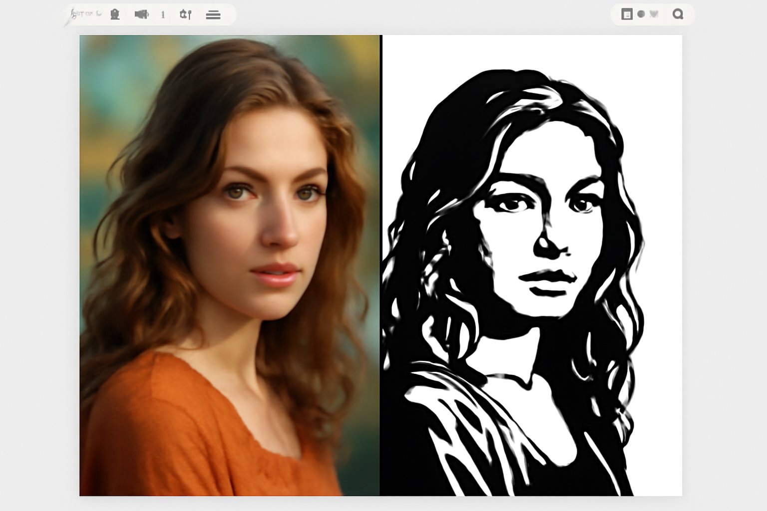
guide · 8 min read
Why Stencils Break When Nothing Fell Out
Islands are the easy failure. Peninsulas, necks that are too thin and spans that are too long are the ones that ruin a stencil while every piece is still attached — and here is what the engine measures to catch them.
StencilVector Team551 views
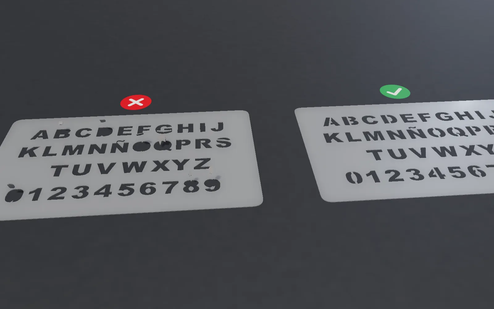
The island problem is the famous one: a piece is completely surrounded by a hole, so it drops on the floor. It is also the easy one, because it is a question you can answer by looking. Either something is detached or it is not.
Most stencils that fail do not fail that way. Nothing falls out. The stencil comes off the cutter looking perfect, and then a tongue of material bends under the roller, or a neck tears on the third use, or a long unsupported edge lifts and lets paint creep underneath. Every piece is still attached. The stencil is still ruined.
This article is about that second category — the failures you cannot see by counting loose pieces — and about what StencilVector measures today to catch them.
Four ways a stencil fails, and only one is an island
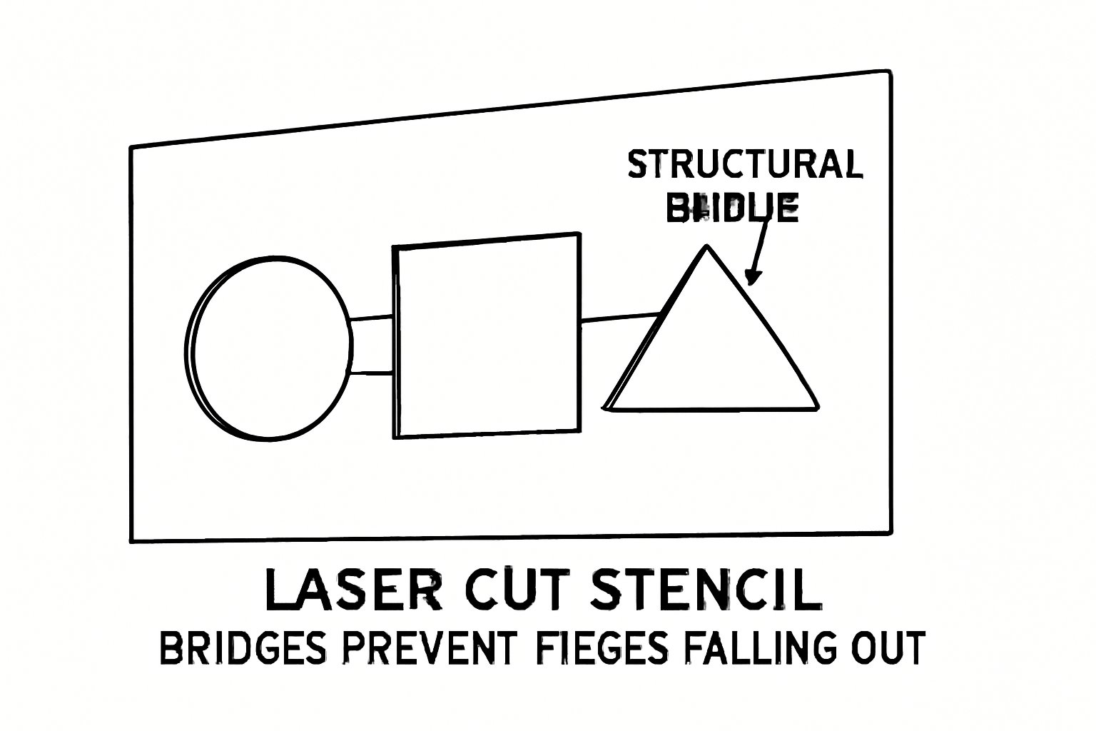
- Islands. Material fully surrounded by a hole. Falls out during cutting. Solved automatically — see how automatic bridges work.
- Peninsulas. Material attached on one side only. It never falls out, so it never counts as an island — but it pivots around its neck, curls under a roller, and lifts at the far end. This is the most common real-world failure and the hardest to see.
- Necks that are too thin. A ligament may be perfectly placed and still be too narrow for the material it is holding. It survives the cut and tears during weeding or on the second use.
- Spans that are too long. A stretch of material with nothing holding it in the middle. It sags away from the surface, and paint runs under the edge.
Only the first is an island. The other three are the reason a stencil with a perfect island score can still be a bad stencil.
The blind spot, measured
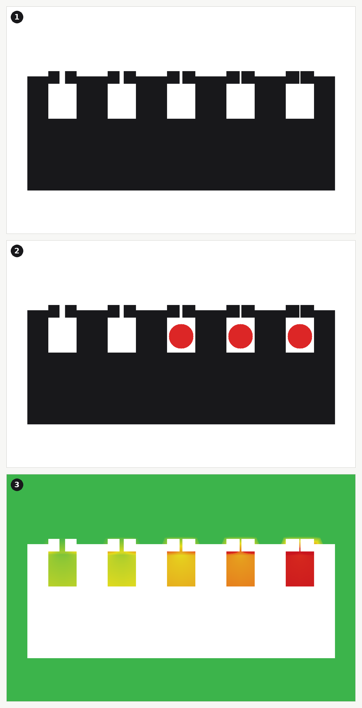
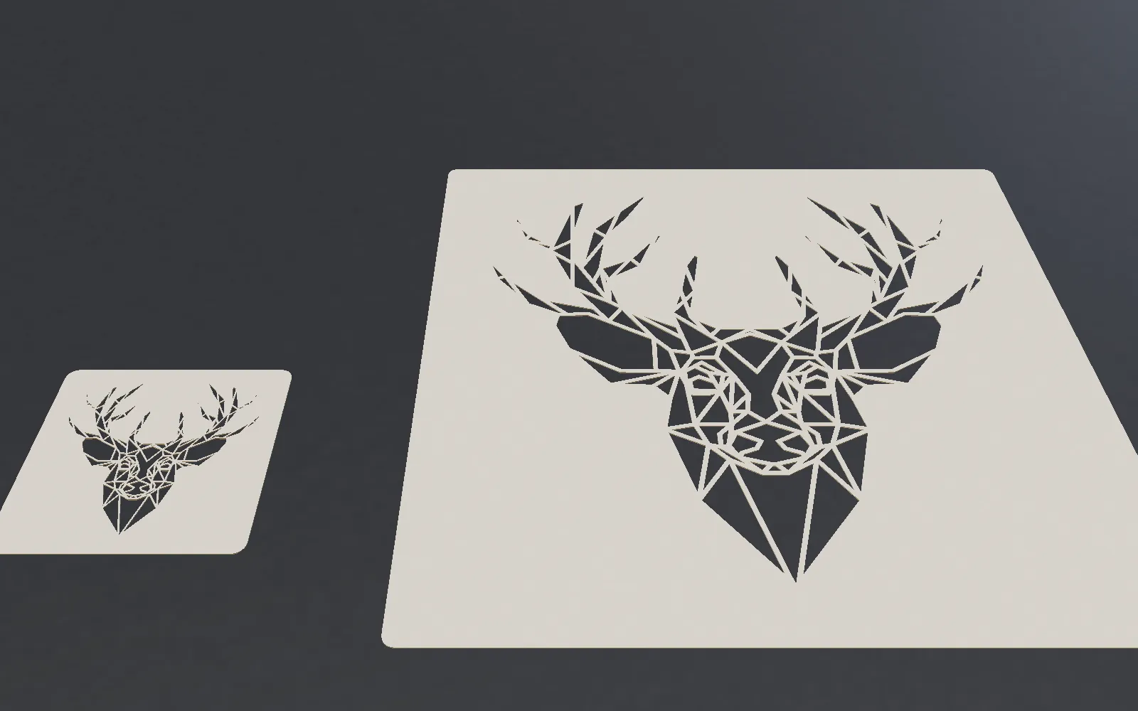
That drawing is deliberately simple, and the numbers from it are worth reading twice:
- Islands found: zero. Island score: 1.00 — a perfect result.
- Support analysis: 0.79. Five parts examined, three of them under-supported.
- The worst: a part of 298 mm² held by 0.8 mm of material where 1.9 mm is required — a ratio of 0.43, flagged critical.
Two honest conclusions follow. First, an island count of zero is not a verdict on the stencil; it only means nothing is loose. Second, StencilVector does not rely on the island count alone — when you preview bridges, the score you see is the support score, not the island ratio.
What the score you see is actually made of
When bridges are previewed, every part of the stencil is measured against the support it has, and the score is the area-weighted average of min(1, support ÷ required) across all parts. Any island counts as zero. A big part that is badly held drags the number down much harder than a small one, which is the behaviour you want.
The simpler island ratio — one minus five times the floating fraction — still exists and is what the first conversion pass reports before any bridge is placed. The two numbers answer different questions: is anything loose versus is everything held well enough.
How much support is "enough", in millimetres
This is the part usually left as a matter of taste. It is not. The required support width for a part is:
- W = 10 mm × √(A ⁄ 2500) × ((L + 10) ⁄ 40)1.2 × (Dref ⁄ D)1/3

where A is the effective area of the part in mm² (including anything hanging off it), L is the lever — the furthest the part reaches from its supports — and D = E·t³ is bending stiffness, referenced to 0.5 mm PET. It never returns less than 1 mm.
Run it and you get a table you can actually design against:
- 100 mm² part (a small detail), lever 10 / 30 / 60 mm → 1.0 / 2.0 / 3.9 mm of support in 0.5 mm PET.
- 400 mm² part (a medium letter), lever 10 / 30 / 60 mm → 1.7 / 4.0 / 7.8 mm.
- 2500 mm² part (a 50×50 panel), lever 10 / 30 / 60 mm → 4.4 / 10.0 / 19.6 mm.
And the same three parts at a 30 mm lever, by material:
- 0.5 mm flexible PET: 2.0 / 4.0 / 10.0 mm
- 1.0 mm PET: 1.0 / 2.0 / 5.0 mm — half as much, because stiffness goes with the cube of thickness
- 0.8 mm stainless: 1.0 / 1.0 / 2.5 mm — roughly a seventh of the thin plastic
One caveat stated plainly, because it explains why these numbers look large: gravity alone would be about a hundred times less demanding. A stencil does not fail hanging still in a room; it fails while being peeled off the backing, carried, pressed down, sprayed and cleaned. The model is calibrated for handling, not for weight.
Why the lever is the number that catches people out
Look again at the 100 mm² row: 1.0 mm of support at a 10 mm lever, 3.9 mm at 60 mm. The part has not gained a single square millimetre. All that changed is how far it reaches from where it is held — and the requirement almost quadrupled.
That is the mathematics of a peninsula. A compact shape held near its centre is easy. The same amount of material stretched into a tongue, held only at the root, is a different structural object. If you take one habit away from this article: look at your longest unsupported reach, not at your smallest feature.
Parts and ligaments: where the line is drawn
Before anything can be measured, the stencil has to be split into what is being held and what is doing the holding. The rule is a width threshold: material narrower than 3.5 mm locally is treated as a ligament, anything wider as a part.
The consequence is the useful insight. A bridge you added and a narrow neck that happened to be in the artwork are the same object to the analysis, because they are the same object physically. Your design is already full of bridges you did not draw; some of them are load-bearing, and some are too thin for the job.
The minimum a neck can ever be
Independently of what it holds, a ligament has a floor set by the material thickness: 2× the thickness up to 0.6 mm, and 2.5× above it.
- 0.5 mm PET → 1.0 mm minimum ligament
- 0.8 mm stainless → 2.0 mm
- 1.0 mm PET → 2.5 mm
Note that this runs the opposite way to intuition: the thicker material needs the wider neck, not the narrower one. A thick neck that is too short in cross-section behaves like a hinge and fails at the fold, and the multiplier itself steps up above 0.6 mm.
The criticality map, and what it really is

The coloured map is worth describing accurately, because it is easy to assume it is something it is not. It is not a stress plot. What it computes is the cheapest path from every point of material back to the solid edge of the sheet, where the cost of crossing a place is one divided by how wide the material is there.
In other words: how far are you from something solid, counting narrowness as distance? A point just behind a 1 mm neck is, structurally, very far away even if it is 2 mm from the frame in a straight line. That is exactly the intuition an experienced cutter has, expressed as a number. Necks below 5 mm add a further penalty, and the whole map is then scaled by the material.
The scale in the picture above is the honest part: identical geometry scores 0.94 in flexible plastic and 1.00 in rigid metal. If you change material at the end of your project, the analysis you did at the beginning no longer applies.
What is handled for you, and what is not
Stated plainly, because the difference matters:
- Handled automatically: islands are found and bridged; specks too small to bridge are removed; every part is checked against its required support and the result is folded into the score you see; the criticality map is generated for the material you selected.
- Left to you in the Stencil Maker: deciding which weak point to fix, and fixing it. The score tells you the stencil is under-supported and the map shows you where the trouble is; you close the gap by hand — thicken a neck or add a connection with the brush, or change the size or the conversion method so the problem does not arise.
- In Vector Studio (beta): Fix automatically: islands + supports adds, in one step, the connections for loose parts and for under-supported ones — and each of them can then be moved, reshaped or undone.
Vector Studio: fixing weak points on the vector
This is exactly the class of problem Vector Studio is for. Since September 2026 it has been in beta as step 4 of the Stencil Maker, Touch-up, on a computer: you see the weak points on the finished vector artwork and correct them there — thickening a neck with the material brush, adding a connection where a span runs too long — with the structural verdict updating as you work. It is a beta, and we would rather say so than oversell it.
Whichever route you take, the practical advice is unglamorous but effective: before you cut, look at the map, find your longest unsupported reach, and widen the neck that holds it.
Related reading: stencil bridge design for the principles, and how automatic bridge generation works for the placement algorithm and the numbers behind it.
Try the free Stencil Maker and look at the criticality map before you send the file to the cutter.
Stencil Maker
Ready to create your own stencil?
Upload any image, check the bridges and download a laser-ready file.